Difference between revisions of "Keymatrix Daughterboards"
From PHCC
| Line 17: | Line 17: | ||
== Theory of Operation == | == Theory of Operation == | ||
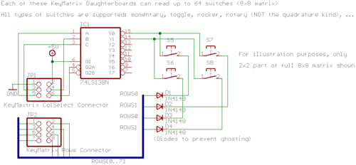
| − | + | [[Image:PHCC_key_overview.png|thumb|center|500px|Keymatrix - Theory of Operation - electrical]]<BR> | |
| − | + | [[Image:PHCC_key64d_PH_switch_wiring.png |thumb|center|500px|Keymatrix - Theory of Operation - Switch Wiring]]<BR> | |
| − | + | ||
== Available or planned PHCC Keymatrix Input Daughterboards == | == Available or planned PHCC Keymatrix Input Daughterboards == | ||
{{KeymatrixDaughterBoardList}} | {{KeymatrixDaughterBoardList}} | ||
Latest revision as of 17:28, 11 November 2008
Keymatrix Inputs
The PHCC system allows you to connect up to 1024 boolean (on/off) inputs. This should be sufficient for most simbuilder's needs (but no all as I've heard :-)
This allows you to connect for example:
- MCP/Autopilot panel
- MIP (main instrument panel)
- CDUs
- pedestal
- overhead
- circuit breakers
- ...
These inputs are arranged in a matrix. The matrix consists of eight columns and 128 rows. The rows are organized in 16 groups of 8 rows. This translates into 16 keymatrix daughterboards with each 64 inputs (arranged as an 8x8 matrix).
Theory of Operation
Available or planned PHCC Keymatrix Input Daughterboards
- KEY64D_PH
- KEY64D_SC35
- KEY64_251 (Strictly speaking NOT in matrix organization. Has one common wire for each input. So, there are 64+1 wires per board.)

