Difference between revisions of "KEY64D PH"
From PHCC
| (2 intermediate revisions by one other user not shown) | |||
| Line 1: | Line 1: | ||
| − | = KEY64D_PH | + | = KEY64D_PH Keymatrix Daughterboard = |
| + | |||
'''Features:''' | '''Features:''' | ||
| Line 8: | Line 9: | ||
== Schematic and Layout == | == Schematic and Layout == | ||
| − | [[Image: | + | |
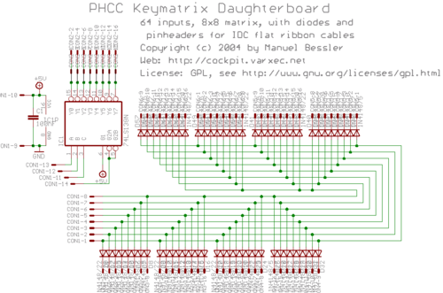
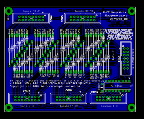
| − | [[Image: | + | [[Image:PHCC key64d ph sch.png|thumb|center|500px|Rev.0 Schematic]]<br> [[Image:PHCC key64d ph brd.png|thumb|center|500px|Rev.0 Layout]]<br> |
== Bill of Materials == | == Bill of Materials == | ||
The BOM is here: [http://cockpit.varxec.net/electronics/phcc/files/PHCC_KEY64D_PH.BOM.txt PHCC_KEY64D_PH.BOM.txt]<br> This list includes prices and links to to online catalogue pages of my primary source of electronics components, [http://www.reichelt.de/ Reichelt Elektronik] | The BOM is here: [http://cockpit.varxec.net/electronics/phcc/files/PHCC_KEY64D_PH.BOM.txt PHCC_KEY64D_PH.BOM.txt]<br> This list includes prices and links to to online catalogue pages of my primary source of electronics components, [http://www.reichelt.de/ Reichelt Elektronik] | ||
| + | |||
| + | North American users Bill of Materials [[media: KEY64D PH Rev0B BOM.pdf]] | ||
| + | |||
| + | == Wiring Switches == | ||
| + | |||
| + | Here is an image that illustrates how to connect switches to the key matrix board. | ||
| + | |||
| + | [[Image:PHCC_key64d_PH_switch_wiring.png|thumb|center|500px|Wiring Diagram]] | ||
| + | |||
| + | |||
| + | In order to correctly wire switches to the KEY64D_PH, you need to carefully follow the matrix layout. | ||
| + | |||
| + | The 64 switch inputs are broken out on the four connectors marked CON3 thru CON6. Each connector has two blocks of 8 inputs. Each one of those blocks matches one pair of pins on the "Common" connector, CON2. | ||
| + | |||
| + | The pins on CON2 thru CON6 are laid out like this: | ||
| + | |||
| + | 15 13 11 9 7 5 3 1<br> | ||
| + | 16 14 12 10 8 6 4 2 | ||
| + | |||
| + | For the Common block, it gives you two attach points for each common line. For example, pins 1 & 2 are bound together to form "Common #1". This is the same for 2-3, 4-5, etc. | ||
| + | |||
| + | Two quick & dirty examples: | ||
| + | To wire in Switch #1, you'll connect one leg of the switch to pin #1 on CON3 and the other leg to either pin 1 or 2 on CON2. | ||
| + | To wire in Switch #9, you'll connect one leg of the switch to pin #9 on CON3 and the other leg to either pin 3 or 4 on CON2. | ||
| + | |||
| + | == Potential Problems == | ||
| + | |||
| + | Note that if you see really odd behavior with your KEY64D_PH with ghosting, or odd input behavior like what has been described in this forum thread: http://forums.varxec.net/index.php?t=msg&th=158&start=0&rid=36 you should carefully check the orientation of the resistor networks on the PHCC motherboard (RN1 & RN2). The "polarity" of the part is important. | ||
Latest revision as of 21:55, 24 December 2008
Contents
KEY64D_PH Keymatrix Daughterboard
Features:
- 64 inputs
- no ghosting as each input is diode protected
- connectors: pinheaders for IDC ribbon flat cables
- board size: 80x100mm (1/2 euro size)
Schematic and Layout
Bill of Materials
The BOM is here: PHCC_KEY64D_PH.BOM.txt
This list includes prices and links to to online catalogue pages of my primary source of electronics components, Reichelt Elektronik
North American users Bill of Materials media: KEY64D PH Rev0B BOM.pdf
Wiring Switches
Here is an image that illustrates how to connect switches to the key matrix board.
In order to correctly wire switches to the KEY64D_PH, you need to carefully follow the matrix layout.
The 64 switch inputs are broken out on the four connectors marked CON3 thru CON6. Each connector has two blocks of 8 inputs. Each one of those blocks matches one pair of pins on the "Common" connector, CON2.
The pins on CON2 thru CON6 are laid out like this:
15 13 11 9 7 5 3 1
16 14 12 10 8 6 4 2
For the Common block, it gives you two attach points for each common line. For example, pins 1 & 2 are bound together to form "Common #1". This is the same for 2-3, 4-5, etc.
Two quick & dirty examples: To wire in Switch #1, you'll connect one leg of the switch to pin #1 on CON3 and the other leg to either pin 1 or 2 on CON2. To wire in Switch #9, you'll connect one leg of the switch to pin #9 on CON3 and the other leg to either pin 3 or 4 on CON2.
Potential Problems
Note that if you see really odd behavior with your KEY64D_PH with ghosting, or odd input behavior like what has been described in this forum thread: http://forums.varxec.net/index.php?t=msg&th=158&start=0&rid=36 you should carefully check the orientation of the resistor networks on the PHCC motherboard (RN1 & RN2). The "polarity" of the part is important.


