DOA 7seg
From PHCC
Revision as of 06:39, 11 November 2008 by WikiAdmin (Talk | contribs) (New page: === DOA_7seg (Rev.1) === Jumper selectable to either *common cathode *common anode Along with the Jumper selection via JP1, the suitable driver chip has to be used for IC4 and IC5. ''...)
Contents
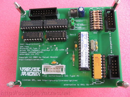
DOA_7seg (Rev.1)
Jumper selectable to either
- common cathode
- common anode
Along with the Jumper selection via JP1, the suitable driver chip has to be used for IC4 and IC5.
Features
- select common cathode or anode via JP1 and IC4/IC5
- 32 displays per board or 256 LEDs or any combination
- small boardsize: 80x100mm or 1/2 Euro size.
- dimming possible
- no ghosting
- hi current displays supported (25mA max. per segment)
- all segments individually controllable
- ie. the dot
- allows you to create certain characters, like a capital 'A' or 'C', a lower case 'd',...
- individual segments fully controllable by host software
- of course, instead of 7segment displays you can also use LEDs (8 LEDs instead of one display, 16 instead of two,...)
- controlled via the PHCC DOA bus with the AP2P Protocol.
- multiple display controllers can be connected to the DOA bus...
- along with other DOA bus devices (up to 256 devices currently)
Example Setup
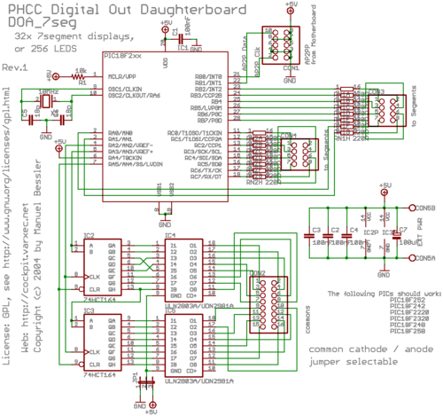
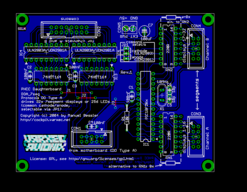
Schematic and Board Layout
Bill of Materials
see download page.
Eagle and Gerber files
see download page.


