Right console
From PHCC
Contents
F16 Right console input breakout board
Features:
- connects to two KEY64D PH board
- each panel has its own connector
- connectors: pin headers for IDC ribbon flat cables
- board size: 160x100mm (full euro size)
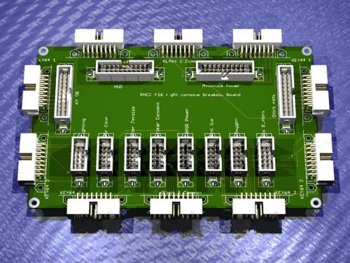
3D view of board
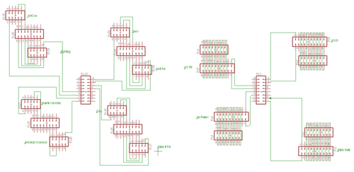
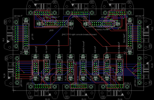
Schematic and Layout
Bill of Materials
TBA
Wiring the breakout board
- Wiring the breakout board to the KEY64D_PH:
one 14 pin cable connects from the KEY64D_PH common to the breakout board common, the rest of the 14 cables connect to either of the 14 pin headers on the board.
- Wiring the panels to the breakout board :
2 types of connectors are available : 10 pin connector and 20 pin connector.
10 pin connector: connecting the panel to the 10 pin header requires connecting the common to pin 1 and 10. all the switches connect to pins 2-9 : not all pins are available on all pin headers, but the count always starts from 2 and on.
20 pin connector: common pins are 1 and 2, pins and 4 are not used. pin 1 is common for the uneven pins - 5,7,9,11,13,15,17,19 pin 2 is common to the even pins - 6,8,10,12,14,16,18,20 on the 20 pin header all the pins are always available.


