Difference between revisions of "KEY64D PH"
From PHCC
| Line 1: | Line 1: | ||
| − | = KEY64D_PH | + | = KEY64D_PH Keymatrix Daughterboard = |
| + | |||
'''Features:''' | '''Features:''' | ||
| Line 8: | Line 9: | ||
== Schematic and Layout == | == Schematic and Layout == | ||
| − | [[Image: | + | |
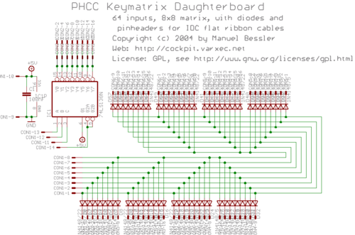
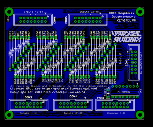
| − | [[Image: | + | [[Image:PHCC key64d ph sch.png|thumb|center|500px|Rev.0 Schematic]]<br> [[Image:PHCC key64d ph brd.png|thumb|center|500px|Rev.0 Layout]]<br> |
== Bill of Materials == | == Bill of Materials == | ||
| − | The BOM is here: [http://cockpit.varxec.net/electronics/phcc/files/PHCC_KEY64D_PH.BOM.txt PHCC_KEY64D_PH.BOM.txt]<br> This list includes prices and links to to online catalogue pages of my primary source of electronics components, [http://www.reichelt.de/ Reichelt Elektronik] | + | The BOM is here: [http://cockpit.varxec.net/electronics/phcc/files/PHCC_KEY64D_PH.BOM.txt PHCC_KEY64D_PH.BOM.txt]<br> This list includes prices and links to to online catalogue pages of my primary source of electronics components, [http://www.reichelt.de/ Reichelt Elektronik] |
| + | |||
| + | == Wiring Switches == | ||
| + | |||
| + | Here is an image that illustrates how to connect switches to the key matrix board. | ||
| + | |||
| + | [[Image:PHCC_key64d_PH_switch_wiring.png|thumb|center|500px|Wiring Diagram]] | ||
| + | |||
| + | |||
| + | In order to correctly wire switches to the KEY64D_PH, you need to carefully follow the matrix layout. | ||
| + | |||
| + | The 64 switch inputs are broken out on the four connectors marked CON3 thru CON6. Each connector has two blocks of 8 inputs. Each one of those blocks matches one pair of pins on the "Common" connector, CON2. | ||
| + | |||
| + | The pins on CON2 thru CON6 are laid out like this: | ||
| + | |||
| + | 15 13 11 9 7 5 3 1<br> | ||
| + | 16 14 12 10 8 6 4 2 | ||
| + | |||
| + | For the Common block, it gives you two attach points for each common line. For example, pins 1 & 2 are bound together to form "Common #1". This is the same for 2-3, 4-5, etc. | ||
| + | |||
| + | Two quick & dirty examples: | ||
| + | To wire in Switch #1, you'll connect one leg of the switch to pin #1 on CON3 and the other leg to either pin 1 or 2 on CON2. | ||
| + | To wire in Switch #9, you'll connect one leg of the switch to pin #9 on CON3 and the other leg to either pin 3 or 4 on CON2. | ||
Revision as of 11:01, 18 December 2008
Contents
KEY64D_PH Keymatrix Daughterboard
Features:
- 64 inputs
- no ghosting as each input is diode protected
- connectors: pinheaders for IDC ribbon flat cables
- board size: 80x100mm (1/2 euro size)
Schematic and Layout
Bill of Materials
The BOM is here: PHCC_KEY64D_PH.BOM.txt
This list includes prices and links to to online catalogue pages of my primary source of electronics components, Reichelt Elektronik
Wiring Switches
Here is an image that illustrates how to connect switches to the key matrix board.
In order to correctly wire switches to the KEY64D_PH, you need to carefully follow the matrix layout.
The 64 switch inputs are broken out on the four connectors marked CON3 thru CON6. Each connector has two blocks of 8 inputs. Each one of those blocks matches one pair of pins on the "Common" connector, CON2.
The pins on CON2 thru CON6 are laid out like this:
15 13 11 9 7 5 3 1
16 14 12 10 8 6 4 2
For the Common block, it gives you two attach points for each common line. For example, pins 1 & 2 are bound together to form "Common #1". This is the same for 2-3, 4-5, etc.
Two quick & dirty examples: To wire in Switch #1, you'll connect one leg of the switch to pin #1 on CON3 and the other leg to either pin 1 or 2 on CON2. To wire in Switch #9, you'll connect one leg of the switch to pin #9 on CON3 and the other leg to either pin 3 or 4 on CON2.


