Difference between revisions of "Center console"
From PHCC
(New page: == F16 Center console input breakout board == '''Features:''' *connects to one KEY64D_PH board *each panel has its own connector *connectors: pin headers for IDC ribbon flat cables...) |
(→Wiring the breakout board) |
||
| (18 intermediate revisions by the same user not shown) | |||
| Line 1: | Line 1: | ||
| − | |||
== F16 Center console input breakout board == | == F16 Center console input breakout board == | ||
| Line 11: | Line 10: | ||
== 3D view of board == | == 3D view of board == | ||
| + | |||
| + | [[Image:Breakout_center_3d.jpg |thumb|center|500px|Rev.0 3D view]] | ||
== Schematic and Layout == | == Schematic and Layout == | ||
| + | |||
| + | [[Image:Breakout_center_sch.PNG |thumb|center|500px|Rev.0 schematics]] | ||
| + | <br/> | ||
| + | [[Image:Breakout_center_brd.PNG |thumb|center|500px|Rev.0 Layout]] | ||
==Bill of Materials == | ==Bill of Materials == | ||
| + | |||
| + | TBA | ||
| + | |||
| + | == Wiring the breakout board == | ||
| + | |||
| + | *'''Wiring the breakout board to the KEY64D_PH:''' | ||
| + | |||
| + | one 14 pin cable connects from the KEY64D_PH common to the breakout board common, the rest of the 14 pin cables connect to either of the 14 pin headers on the board. | ||
| + | |||
| + | *'''Wiring the panels to the breakout board :''' | ||
| + | |||
| + | 2 types of connectors are available : 10 pin connector and 20 pin connector. | ||
| + | |||
| + | '''10 pin connector:''' connecting the panel to the 10 pin header requires connecting the common to pin 1 and 10. all the switches connect to pins 2-9 : not all pins are available on all pin headers, but the count always starts from 2 and on. | ||
| + | |||
| + | '''20 pin connector:''' common pins are 1 and 2, pins and 4 are not used. pin 1 is common for the uneven pins - 5,7,9,11,13,15,17,19 pin 2 is common to the even pins - 6,8,10,12,14,16,18,20 on the 20 pin header all the pins are always available. | ||
Latest revision as of 09:13, 25 December 2008
Contents
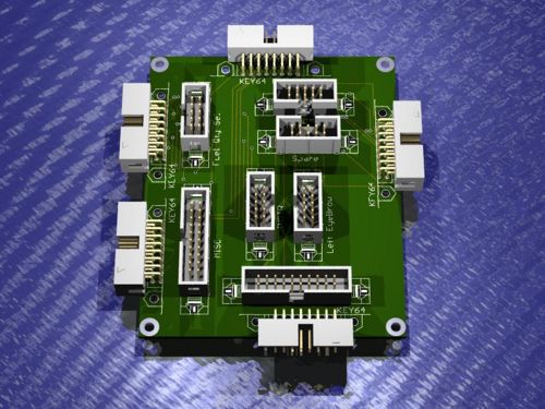
F16 Center console input breakout board
Features:
- connects to one KEY64D_PH board
- each panel has its own connector
- connectors: pin headers for IDC ribbon flat cables
- board size: 80x100mm (1/2 euro size)
- this board DOES NOT support the MFD's and ICP
3D view of board
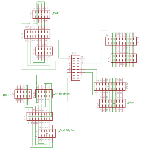
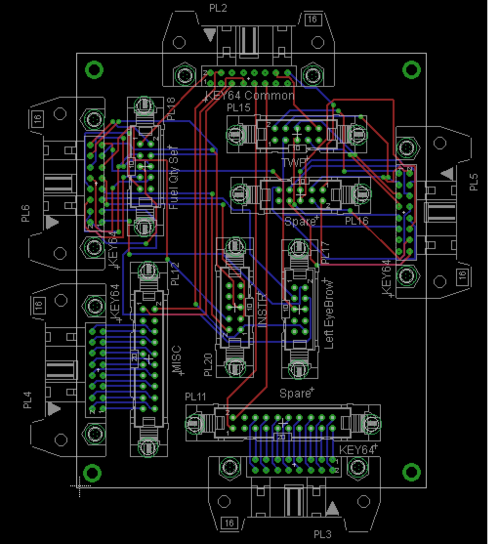
Schematic and Layout
Bill of Materials
TBA
Wiring the breakout board
- Wiring the breakout board to the KEY64D_PH:
one 14 pin cable connects from the KEY64D_PH common to the breakout board common, the rest of the 14 pin cables connect to either of the 14 pin headers on the board.
- Wiring the panels to the breakout board :
2 types of connectors are available : 10 pin connector and 20 pin connector.
10 pin connector: connecting the panel to the 10 pin header requires connecting the common to pin 1 and 10. all the switches connect to pins 2-9 : not all pins are available on all pin headers, but the count always starts from 2 and on.
20 pin connector: common pins are 1 and 2, pins and 4 are not used. pin 1 is common for the uneven pins - 5,7,9,11,13,15,17,19 pin 2 is common to the even pins - 6,8,10,12,14,16,18,20 on the 20 pin header all the pins are always available.


