Difference between revisions of "DOA 40DO"
From PHCC
(→Bill of Materials) |
|||
| (5 intermediate revisions by 3 users not shown) | |||
| Line 9: | Line 9: | ||
*open collector outputs (sinking action) | *open collector outputs (sinking action) | ||
*uses DOA protocol | *uses DOA protocol | ||
| + | |||
| + | Note: | ||
| + | If needed the same board layout can be used for current sourcing outputs: | ||
| + | |||
| + | |||
| + | Replace the original ULN2803 by UDN2981. | ||
| + | Reverse the polarity of C10. | ||
| + | Do '''not''' mount or remove R9. | ||
| + | Connections to CON2 have to be reversed. | ||
| + | GND becomes +Vout and +Vout becomes GND | ||
| + | |||
| + | <blockquote>UDN2981 sometimes is known as UTC62783 or TD62783AP, | ||
| + | depends on manufacturer and/or seller.</blockquote> | ||
===== Schematic and Layout ===== | ===== Schematic and Layout ===== | ||
| Line 27: | Line 40: | ||
see [http://cockpit.varxec.net/electronics/phcc/download.html#DOA_40DO download page]. | see [http://cockpit.varxec.net/electronics/phcc/download.html#DOA_40DO download page]. | ||
| − | North American users Bill of Materials [[DOA 40DO Rev0 BOM.pdf]] | + | North American users Bill of Materials [[media: DOA 40DO Rev0 BOM.pdf]] |
===== Eagle and Gerber files ===== | ===== Eagle and Gerber files ===== | ||
see [http://cockpit.varxec.net/electronics/phcc/download.html#DOA_40DO download page]. | see [http://cockpit.varxec.net/electronics/phcc/download.html#DOA_40DO download page]. | ||
Latest revision as of 17:58, 1 February 2021
Contents
DOA_40DO
40 Channel Digital Output Daughterboard.
Features:
- 40 channels
- up to 125mA per channel (continous)
- up to 50V
- open collector outputs (sinking action)
- uses DOA protocol
Note: If needed the same board layout can be used for current sourcing outputs:
 Replace the original ULN2803 by UDN2981.
 Reverse the polarity of C10.
 Do not mount or remove R9.
 Connections to CON2 have to be reversed.
 GND becomes +Vout and +Vout becomes GND
UDN2981 sometimes is known as UTC62783 or TD62783AP, depends on manufacturer and/or seller.
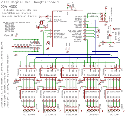
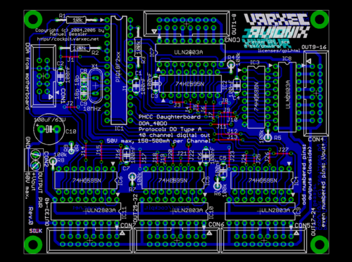
Schematic and Layout
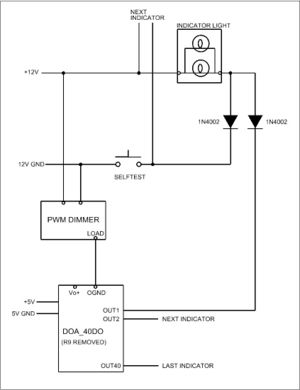
Interconnection
Typical connection for 12 volt indicators with dimming circuit and selftest (Note: no connection on Vo+)
A note to DIYers
This board is so far one of the hardest for DIY. Lots of thin traces with spacings of often just 8mils. In addition, several wire bridges (for single-sided boards) / top side traces (for double-sided boards) are very close to IC pads. These facts make this particular board a challenge for people who are not regularly etching PCBs at home. For details, go ask on the PHCC forum.
Bill of Materials
see download page.
North American users Bill of Materials media: DOA 40DO Rev0 BOM.pdf
Eagle and Gerber files
see download page.


