Difference between revisions of "DOA AnOut1"
From PHCC
| (One intermediate revision by one other user not shown) | |||
| Line 1: | Line 1: | ||
| − | + | = DOA_AnOut1 = | |
| − | + | ||
| − | + | ||
| − | + | ||
| − | + | ||
| − | + | ||
| − | + | ||
| − | + | ||
| − | + | ||
| − | + | ||
| − | + | ||
| − | + | ||
| − | + | ||
| − | + | ||
| − | + | ||
| − | + | ||
| − | + | ||
| − | + | ||
| − | + | ||
| − | + | ||
| − | + | ||
| − | + | ||
| − | + | ||
| − | + | ||
| − | + | ||
| − | + | ||
| − | + | ||
| − | + | ||
| − | + | ||
| − | + | ||
| − | + | ||
| − | + | ||
| − | + | ||
| − | + | ||
| − | + | ||
| − | + | ||
| − | + | ||
| − | + | ||
| − | + | ||
| − | + | ||
| − | + | ||
'''Features:''' | '''Features:''' | ||
| Line 51: | Line 11: | ||
*software controllable refresh rate (usually called "PWM period") | *software controllable refresh rate (usually called "PWM period") | ||
| − | + | == Schematic and Layout == | |
| − | + | === Rev.0B === | |
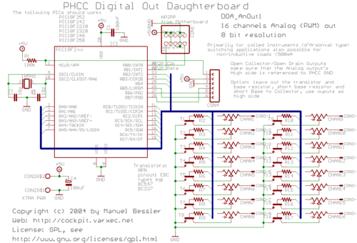
[[Image:PHCC_DOA_AnOut1_sch.png|thumb|center|500px|Rev.0B Schematic]]<BR> | [[Image:PHCC_DOA_AnOut1_sch.png|thumb|center|500px|Rev.0B Schematic]]<BR> | ||
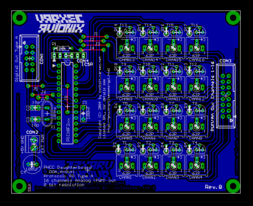
[[Image:PHCC_DOA_AnOut1_brd.png|thumb|center|500px|Rev.0B Layout]]<BR> | [[Image:PHCC_DOA_AnOut1_brd.png|thumb|center|500px|Rev.0B Layout]]<BR> | ||
| − | + | === Rev.0C === | |
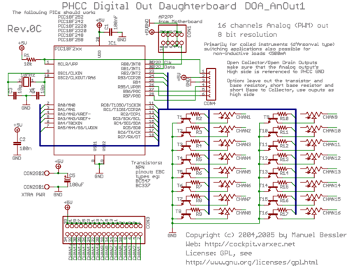
[[Image:PHCC_DOA_AnOut1_rev0c_sch.png|thumb|center|500px|Rev.0C Schematic]]<BR> | [[Image:PHCC_DOA_AnOut1_rev0c_sch.png|thumb|center|500px|Rev.0C Schematic]]<BR> | ||
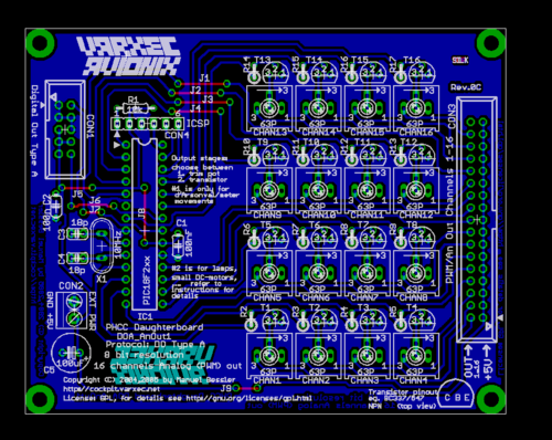
[[Image:PHCC_DOA_AnOut1_rev0c_brd.png|thumb|center|500px|Rev.0C Layout]]<BR> | [[Image:PHCC_DOA_AnOut1_rev0c_brd.png|thumb|center|500px|Rev.0C Layout]]<BR> | ||
| − | + | == Assembly Instructions == | |
Formats available: | Formats available: | ||
| Line 68: | Line 28: | ||
*PDF version: [http://cockpit.varxec.net/electronics/phcc/tutorials/AnOut1_assembly_tutorial.pdf AnOut1_assembly_tutorial.pdf] | *PDF version: [http://cockpit.varxec.net/electronics/phcc/tutorials/AnOut1_assembly_tutorial.pdf AnOut1_assembly_tutorial.pdf] | ||
| − | + | == Bill of Materials == | |
see [http://cockpit.varxec.net/electronics/phcc/download.html#DOA_AnOut1 download page]. | see [http://cockpit.varxec.net/electronics/phcc/download.html#DOA_AnOut1 download page]. | ||
| − | + | North American users Bill of Materials [[media: DOA AnOut1 rev0c BOM.pdf]] | |
| + | |||
| + | == Eagle and Gerber files == | ||
see [http://cockpit.varxec.net/electronics/phcc/download.html#DOA_AnOut1 download page]. | see [http://cockpit.varxec.net/electronics/phcc/download.html#DOA_AnOut1 download page]. | ||
| − | + | == Changes between Revisions: == | |
{| cellpadding="5" class="plain" | {| cellpadding="5" class="plain" | ||
Latest revision as of 21:51, 24 December 2008
Contents
DOA_AnOut1
Features:
- 16 channels
- 8 bit resolution
- uses DOA protocol
- primarily for d'Arsonval type of instruments
- other light loads can also be controlled with the built-in transistor outputs, eg to control cooling fan speed or dimmable lamps.
- open collector outputs, max 45V (or more, depending on transistor)
- software controllable refresh rate (usually called "PWM period")
Schematic and Layout
Rev.0B
Rev.0C
Assembly Instructions
Formats available:
- all in one big HTML page: AnOut1_assembly_tutorial.html
- PDF version: AnOut1_assembly_tutorial.pdf
Bill of Materials
see download page.
North American users Bill of Materials media: DOA AnOut1 rev0c BOM.pdf
Eagle and Gerber files
see download page.
Changes between Revisions:
| Rev.0C | No functional changes. The outputs now feature a connector with more pins. The pinout on this connector thus changed. The odd-numbered pins all carry +5V, while the signals are on the even-numbered pins. Also added one capacitor, C2. Capacitor numbering changed as well. |
| Rev.0B | First public release. |


